Rudder Assembly
This post is largely a back-fill from memory a month after completion of the rudder. I got wrapped up in the build and didn’t take many notes or pictures of the vertical stabilizer or rudder, so I’ll just hit the high (and low) points of the rudder assembly (the vertical stabilizer went really smoothly so there’s not much to talk about there).
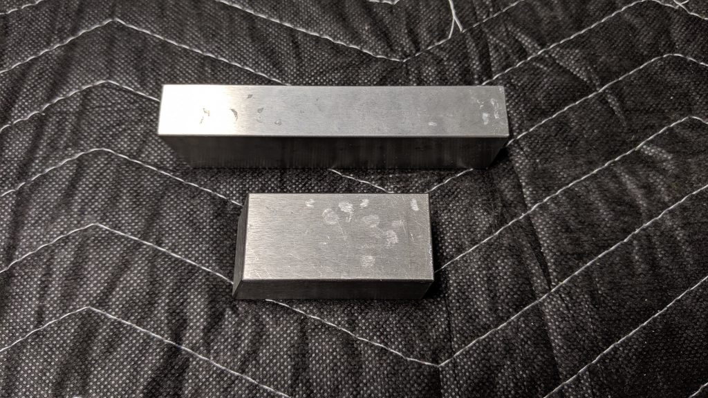
The rudder build was…interesting…to say the least. A few new skills and techniques had to be learned, and while they are interesting and enjoyable, they slow the build significantly. Realizing you don’t have the right tools for the job is also an annoyance that slows the build. I had to buy the mini tungsten bucking bar from Cleaveland Tool just to hit the last couple of rivets inside the rudder horn on page 07-10 of the plans:
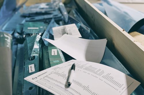
The first few pages of the build were the usual: trim pieces, match/final drill, debur holes and edges, dimple, scuff, clean, and prime.
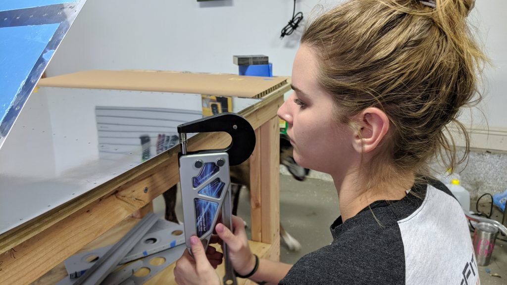
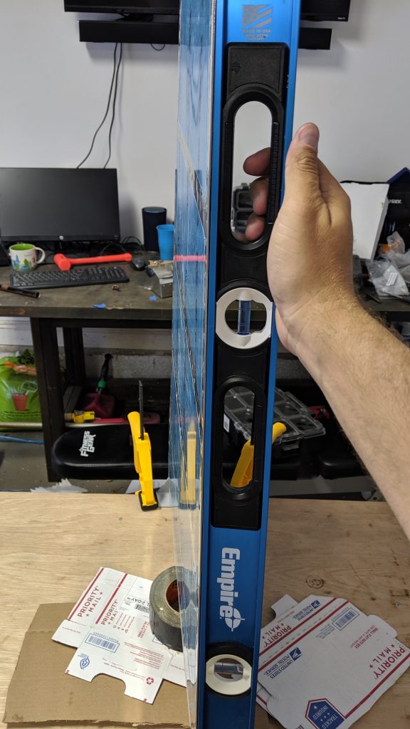
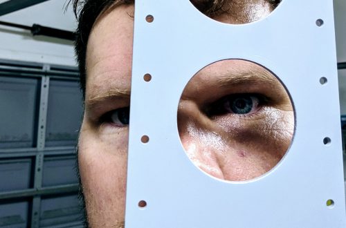
Next up: drilling the trailing edge of the rudder. The trailing edge is an aluminum wedge that sits between the two rudder skins where they come to a point. The tricky part there was the angle of the drill. The plans call out that the holes in the trailing edge should be perpendicular to the chord line of the trailing edge wedge, not the face of the wedge. I eventually worked out that the chord line of the wedge is about 6°. I was able to drill perpendicular to the chord line by using an angle finder set at 84°, resting one side of the angle finder on the rudder skin and using the other side of the angle finder as a guide for the drill placement. It wasn’t a precise method but it turned out well.
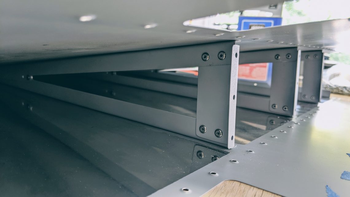
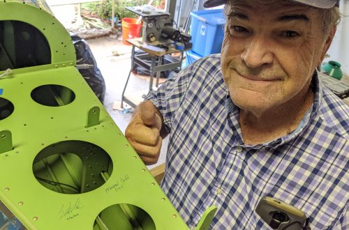
The next daunting task was back-riveting the stiffeners to the rudder skins. I went into this part of the build a little unsure of the technique but it turned out to be really easy with a back rivet set and 12″ back rivet plate. But that is where Easy Street ended and Well That Sucks Boulevard began. After riveting the stiffeners to the rudder skins, page 07-09 calls for riveting the stiffeners from one skin to the other, but specifically calls out that stiffeners attached to the left skin sit above the right skin stiffeners. Easy enough. However, the plans also call out that the forward end of both stiffeners should be under the shear clips. With all the attention we paid to making sure that the aft part of the stiffeners were in correct alignment, we managed to forget the alignment of the stiffeners under the shear clips and ended up with this royal debacle:
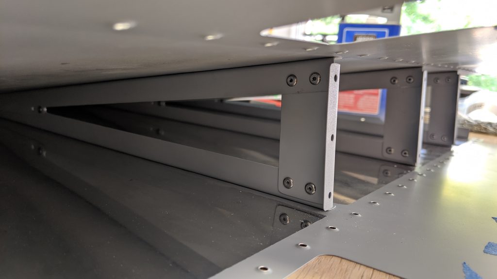
Each one of those blind rivets on the stiffeners sitting on top of the shear clips (and the aft-most blind rivet you can see on the far left) had to be drilled out so the stiffener could be positioned correctly under the shear clip. That was an exercise in patience!
Here’s a time-lapse of the rudder assembly all the way up to the stiffener gaff:
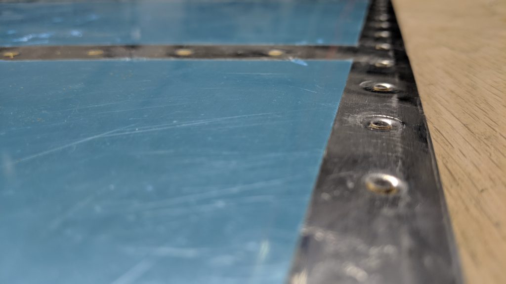
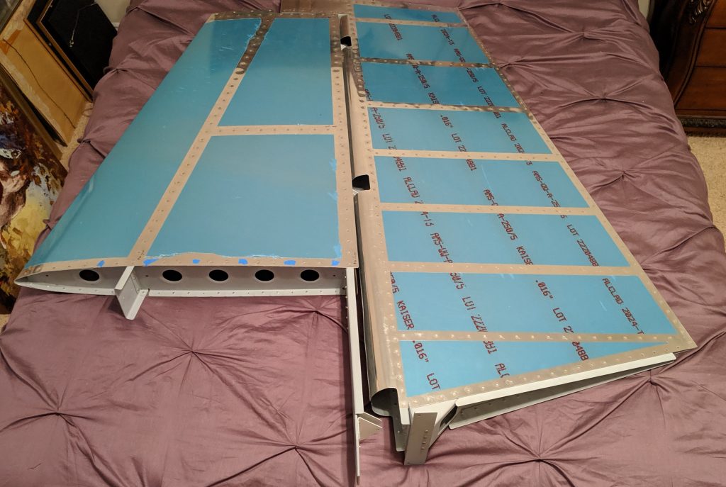
The last new experience brought forth by the rudder assembly was the riveting of the trailing edge. For the trailing edge of the rudder (and other control surfaces), the rivets on both sides of the surface must be flush. To do this, I used a back rivet set to partially set the rivets as per the plans and finished setting the rivets flush with a mushroom set. The results turned out well, in my opinion. I have a straight trailing edge with flush rivets on both sides!
Total build time: 36 hours


You May Also Like
I Don’t Know What I’m Doing
Empennage Completion