The Elevators Begin!
I’ve been home this week for professional training so I’ve been a little closer to the garage which has allowed me to sneak in a few minutes when I break for lunch every day. It also means that I’m that much closer to the airplane when I stop for the day; all the extra few minutes really pays off over time!
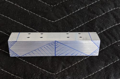
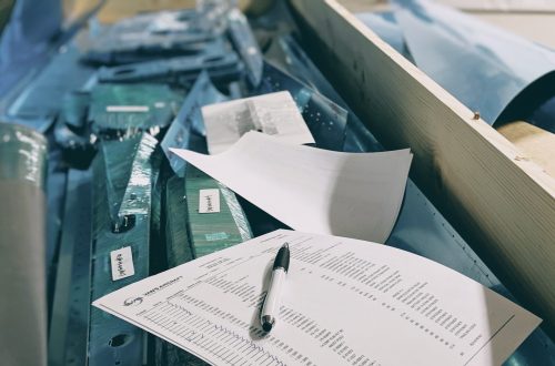
So this week I started on the elevators. The plans first call for separating the square-ish ribs and cleco-ing them back together to form the ribs that will help support the elevator structure.
Next up were the tip ribs. I’m not sure why the plans call for them to be done so early on since you just set them aside when done, but when I disagree with the plans I do what I want. I don’t let the plans boss me around. So I went ahead and completed the tip ribs as described in the plans. 🙂
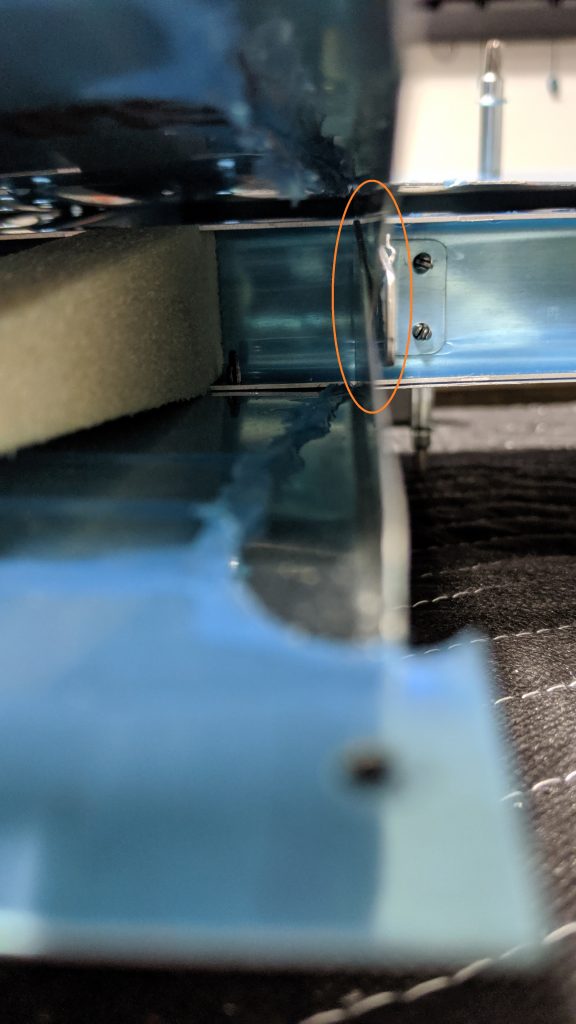
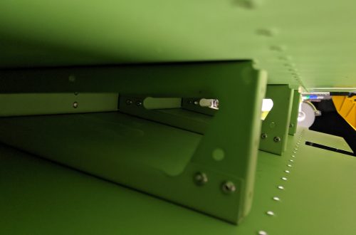
Once the ribs were cleco’d together it was time to do a little work on the skins. Page 09-03 calls for the close-out tabs on the left elevator skins to be bent 90° to the inside. After carefully setting up the skins on the workbench as directed, I made two great, smooth bends that lined up perfectly once the skins were mocked up together. Unfortunately, when I got to page 09-09 where it requires match drilling the shear clip into the close-out tabs I realized something was amiss:
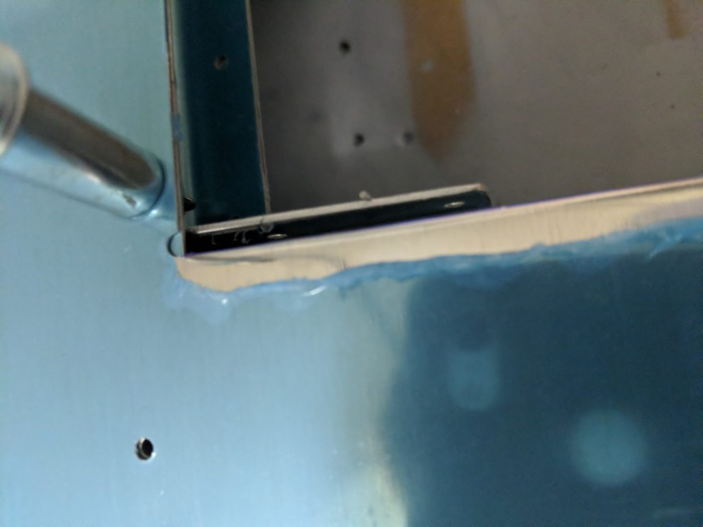
As it turns out, I didn’t pay enough attention to where exactly the bend line was supposed to be made:
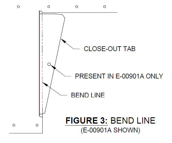
So I guess a call to Vans in the morning is in order…sigh. It doesn’t appear that the shear clip and close-out tabs provide any real structural integrity, and there’s space on the rear spar to move the shear clip so my hope is that I can simply flip the shear clip around to face the other direction and install it that way:
After that snafu, and before I realized I had made the mistake, work on the elevators was happily moving along. Next up: placing the trim tab hinge. I did end up calling Vans when it came time to drill the pilot holes in the trailing edge. The plans demonstrate the measurements for the pilot holes in the forward and aft halves with the specific note, “Verify the fore and aft hinge width…”:
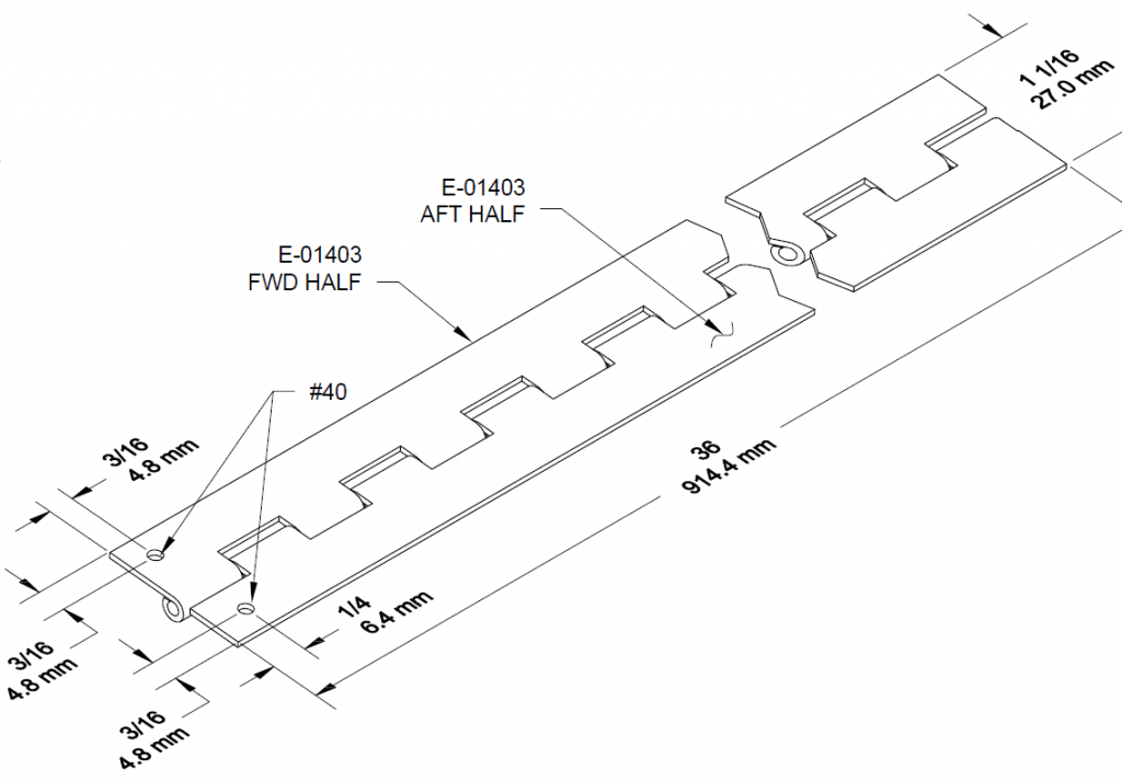
My hinge widths were opposite of what is shown on the far left in the diagram above. That is, the aft half had the eyelet and the forward half did not so I got confused as to whether the pilot holes were based off of the widths as shown above or simply which side was designated forward or aft. So a quick call to Vans confirmed that the hole measurements should be based on forward and aft, not on which side has the eyelet. Sometimes you just can’t not think about things the wrong way, ya know? Anyway, after that I got the piano hinge mounted on the spars (although not pictured, I did reassemble both the forward and aft halves of the piano hinge to verify alignment and hingey-ness…smooth as silk!):
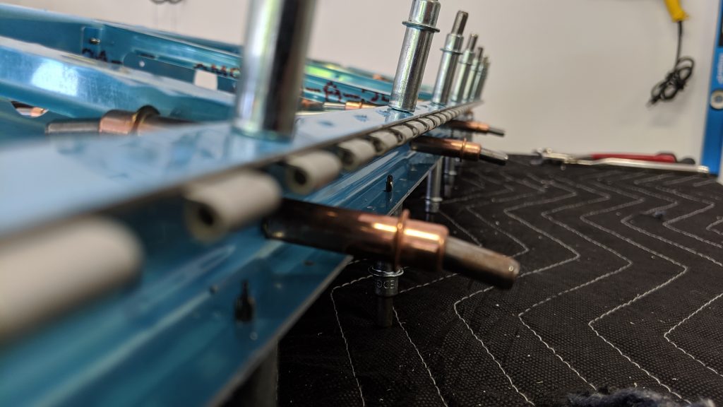
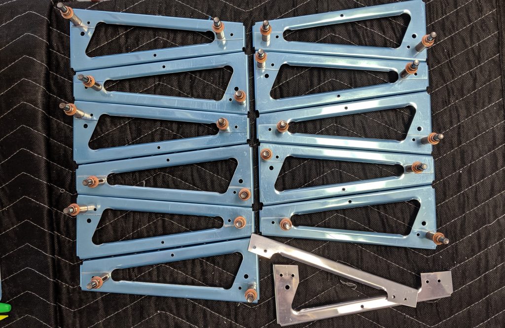
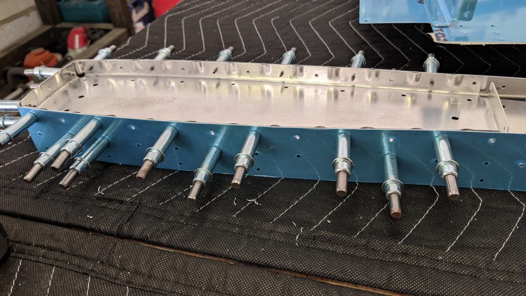
The remainder of the progress was to assemble the elevators with the bottom skins attached. It was a very simple, quick process for a few pages. The general assembly went something like this: attach root ribs to front and rear spars, attach ribs, and then attach it all the the bottom skins for the left and right elevators. Easy peasy.
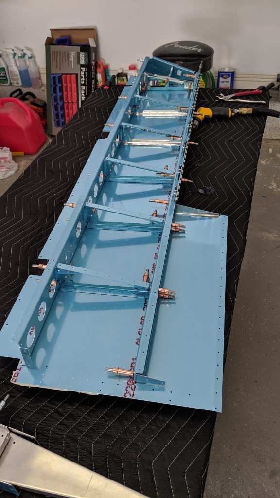
I ended up on page 09-09, where I decided the aforementioned close-out tab mishap was a good place to take a break.


You May Also Like
Rivets and Hardware and Skins, Oh My!
Changing up the Primer Game